


Aero Vodochody L-39C Albatros
Czechoslovak, Two-seat Basic and Advanced Jet Trainer
.jpg)
Archive Photos 1,2
1987 Aero Vodochody L-39C Albatros (N139JT, s/n 734156) on display (6/25/2000) at the 2000 Aviation Expo, Van Nuys Airport, Van Nuys, California (Photos by John Shupek) 1
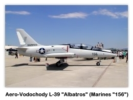
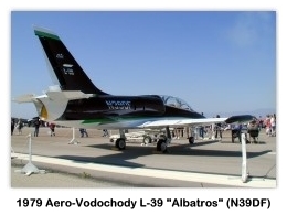
1979 Aero Vodochody L-39C Albatros (N39DF, s/n 931320) on display (4/8/2000) at the 2000 NAS Point Mugu, California (Photos by John Shupek) 1
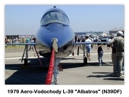
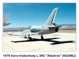
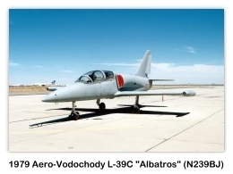
1979 Aero Vodochody L-39C Albatros (N239BJ, s/n 931510) on display (c.1987) at the Mojave Airport, Mojave, California (Photos by John Shupek) 1
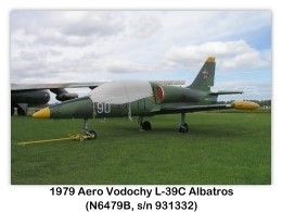
1979 Aero Vodochody L-39C Albatros (N4679B, s/n 931332) on display (9/29/2003) at the Kalamazoo Aviation History Museum, Portage, Michigan (Photos by John Shupek) 1
1976 Aero Vodochody L-39C Albatros (NX143XX, s/n 630648) photographed on (1/5/2012) at the Phoenix Deer Valley Airport (Photos copyright © 2012 Lt. Col. Dr. Marc Matthews, M.D., USAF (retired)) 2


1980 Aero Vodochody L-39C Albatros (NX151XX, s/n 031616) photographed on (1/5/2012) at the Phoenix Deer Valley Airport (Photos by Lt. Col. Dr. Marc Matthews, M.D., USAF (retired)) 2


Aero L-39C Albatros 3
The Aero Vodochody L-39C Albatros basic and advanced jet trainer was developed in the Aero works at Vodochody by a team led by the chief designer, Dipl Ing Jan Vlcek, working in close cooperation with the USSR. Two prototype airframes were built initially, of which the first was used for structural testing. The first flight, on 4 November 1968, was made by the second aircraft. By the end of 1970, five flying prototypes and two for ground testing had been completed. Slightly larger and longer intake trunks were fitted after preliminary flight tests.
The L-39 Albatros forms part of a comprehensive training system which includes a specially designed pilot training flight simulator (TL-39), a pilot ejection ground training simulator (NK-TL-29/39), and vehicle-mounted mobile test equipment (AKC-KL-39). The aircraft is capable of operation from grass strips (with a bearing strength of 6 kg/cm²; 85 psi) up to 4,600 kg (10,141 lbs) T-O weight, or from unprepared runways.
By May 1977, when the Aero L-39 Albatros made its first appearance in the West, at the Paris Air Show, some 400-500 were in service with several air forces. Production had totaled almost 1,000 by the early 1981. The Aero L-39 Albatross is used in Czechoslovakia for all pilot training, including that of helicopter pilots. On average, pupils solo after approximately 12 hours’ dual instruction on the Aero L-39 Albatros.
Official Czechoslovak designations for the different Aero L-39 versions are as follows:
- Aero L-39C Albatros: (’C’ for Cvicný training). Basic and advanced flying training version, to which the following detailed description chiefly applies. In service with the air forces of Afghanistan, Czechoslovakia, Germany (Democratic Republic) and the USSR.
- Aero L-39Z0 Albatros: (’Z’ for Zbrojní: armed). Jet trainer with four underwing weapon stations and reinforced wings. Export customers include the air forces of Iraq and Libya.
- Aero L-39Z Albatros: (’Z’ for Zbrojní: armed). Weapon system training, ground attack and reconnaissance version, with under-fuselage gun and four underwing weapon stations; reinforced wings and landing gear.
Aero L-39C Albatros Specifications 3
The following description applies to the production L-39C trainer version, except where indicated:
Type
- Two-seat basic and advanced jet trainer.
Wings
- Cantilever low-wing monoplane, with 2° 30’ dihedral from roots.
- Wing section NACA 64A012 mod. 5. Incidence 2°.
- Sweepback 6° 26’ on leading-edges, 1° 45’ at quarter-chord.
- One-piece all-metal stressed-skin structure, with main spar and auxiliary spar; four-point attachment to fuselage.
- All-metal double-slotted trailing-edge flaps, operated by push/pull rods actuated by a single hydraulic jack.
- Flaps retract automatically when Airspeed reaches 167 kn (310 km/h; 193 mph).
- Small fence above and below each trailing-edge between flap and aileron.
- Electronically-operated servo tab in each aileron; port tab, used also for trim, is operated by electromechanical actuator.
- Flaps deflect 25° for take-off, 44° for landing; aileron’s deflect 16° up or down; air brakes deflect 55° downward.
- Non-jettisonable wingtip fuel tanks, incorporating landing/taxiing lights.
Fuselage
- Metal semi-monocoque structure, built in two portions.
- Front portion consists of three sections, the first of which is a laminated glass-fibre nose cone housing avionics, antenna, battery, compressed air and oxygen bottles for the nose landing gear.
- Next comes the pressurized compartment for the crew.
- The third section incorporates the fuel tanks, air intakes and the engine bay.
- The rear fuselage, carrying the tail unit, is attached by five bolts and can be removed quickly to provide access for engine installation and removal.
- Two air brakes side-by-side under fuselage, just forward of wing leading edge, Actuated by single hydraulic jack; these are lowered automatically as Airspeed nears a maximum of Mach 0.8.
Tail Unit
- Conventional all-metal cantilever structure, with sweepback on vertical surfaces.
- Variable-incidence tailplane.
- Control surfaces actuated by pushrods.
- Electrically-operated trim tab in each elevator; servo tab and rudder.
- Elevators deflect 30° up, 20° down; rudder 30° to right and left.
Landing Gear
- Retractable tricycle type, with single wheel and oleo-pneumatic shock-absorber on each unit.
- Gear is designed for touchdown sink rate of 3.4 m/s (11.15 ft/s at AUW of 4,600 kg (10,141 lbs).
- Retraction/extension is operated hydraulically, with electrical control.
- All wheel-well doors close automatically after wheels are lowered, to prevent ingress of dirt and debris.
- Main wheels retract inward into wings (with automatic braking during retraction), nosewheel forward into fuselage.
- K24 main wheels, fitted with Barum tubeless tires size 610 × 215 mm (610 × 185 mm on early production aircraft), pressure 5.88 bars (85.34 psi).
- K25 castoring in self-centering nosewheel, fitted with Barum tubeless tire size 450 × 165 mm (430 × 150 mm on early production aircraft), pressure 3.92 bars (56.89 psi).
- Hydraulic disc brakes and anti-skid units on main wheels; shimmy damper on nosewheel leg.
Power Plant
- One 16.87 kN (3,792 lb st) Ivchenko AI-25-TL turbofan engine mounted in rear fuselage, with semi-circular lateral air intake, fitted with splitter plate, on each side of fuselage above wing center-section.
- Fuel in five rubber bag-type main tanks aft of cockpit, with combined capacity of 1,055 L (232 Imp gallons), and two 100 L (22 Imp gallons) non-jettisonable wingtip tanks.
- Total internal fuel capacity 1,255 L (276 Imp gallons).
- Gravity refueling points on top of fuselage and on each tipped tank.
- Provision for two 150 or 350 L (33 or 77 Imp gallons) underwing drop-tanks, increasing total overall fuel capacity to 1,955 L (430 Imp gallons).
- Fuel system permits up to 20 seconds of inverted flight.
Accommodation
- Crew of two in tandem, on VS-1-BR1 rocket-assisted ejection seats, operable at zero height and at speeds down to 81 knots (150 kph; 94 mph), beneath individual transparent canopies which hinge sideways to starboard and are jettisonable.
- One-piece windscreen hinges forward to provide access to front instrument panel.
- Internal transparency between front and rear cockpits.
- Dual controls standard.
Systems
- Cabin pressurized (max differential 0.23 bars; 3.34 psi) and air-conditioned, using engine bleed air and cooling unit.
- Air-conditioning system provides automatic temperature control from 10° to 25°C at ambient air temperatures from -55°C to +45°C.
- Main and standby interconnected hydraulic systems, the main system having a variable-flow pump with an operating pressure of 147 bars (2,133 psi) for actuation of landing gear, flaps, air brakes, ram-air turbine and wheel brakes.
- Emergency system, for all of the above except air brakes, incorporates three accumulators.
- Pneumatic canopy seals supplied by one 2 liter compressed air bottle in nose (pressure 147 bars; 2,133 psi).
- Electrical system (28.5 V DC) is powered by a 9 kW VG 7500JA engine-driven generator.
- If primary generator fails, a V 910 ram-air turbine is extended automatically into the airstream and generates up to 3 kW of emergency power for essential services.
- 12V 28 Ah lead-acid battery for standby power and for APU starting.
- Two 800VA static inverters (the first for radio equipment, ice warning lights, engine vibration measurement and air-conditioning, the second for navigation and landing systems, IFF and air-to-air missiles) provide 115 V single-phase AC power at 400 Hz.
- A second circuit incorporates a 500 VA rotary inverter and 40 VA static inverter to provide three-phase AC power, also a 400 Hz.
- Sapphire 5 APU and SV-25 turbine for engine starting.
- Air intakes and windscreen anti-iced by engine bleed air; normally, anti-icing is sensor-actuated automatically, but a manual standby system is also provided.
- Six-bottle oxygen system for crew, pressure 147 bars (2,133 psi).
Standard Electronics Include
- R-832 M two-band radio (VHF 118-140 MHz
- UHF 220-389 MHz)
- SPU-9 crew intercom
- RKL-41 ADF (150-1,800 kHz)
- RV-5 radio altimeter
- MRP-56 P/S marker beacon receiver
- SRO-2 IFF
- RSBN-5S navigation and landing system.
- VOR/ILS system available at customer’s option.
- Landing and taxiing light in forward end of each tip-tank.
Dimensions
- Wing span: 31 ft 0.5 in (9.46 m)
- Wing chord (mean): 7 ft 0.5 in (2.15 m)
- Wing aspect ratio (geometric): 4.4
- Length overall: 39 ft 9.5 in (12.13 m)
- Height overall: 15 ft 7.75 in (4.77 m)
- Tailplane span: 14 ft 5 in (4.40 m)
- Wheel track: 8 ft 0 in (2.44 m)
- Wheelbase: 14 ft 4¾ in (4.39 m)
Areas
- Wings, gross: 202.36 ft² (18.80 m²)
- Ailerons (total): 13.26 ft² (1.23 m²)
- Trailing-edge flaps (total): 28.89 ft² (2.68 m²)
- Airbrakes, total: 5.38 ft² (0.50 m²)
- Vertical tail surfaces: 37.78 ft² (3.51 m²)
- Tailplane: 42.30 ft² (3.93 m²)
- Elevators, including tabs: 12.27 ft² (1.14 m²)
Weights and Loadings
- Weight empty: 7,859 lb (3,565 kg)
- Crew: 352 lbs (160 kg)
- Fuel load: 1,816 lbs (824 kg)
- Max T-O weight: 10,028 lbs (4,549 kg)
- Max landing weight: 9,480 lbs (4,300 kg)
- Wing loading (clean): 49.77 lbs/ft² (243 kg/m²)
- Power loading (clean): 2.65 lbs/lb st (270.9 kg/kN)
Performance
Configuration ’A’ = ’Clean’ with AUW of 10,075 lbs (4,570 kg) with tip-tanks empty
Configuration ’C’ = AUW of 9,480 lbs (4,300 kg)
- Max limiting Mach number (VNE) above 1,300 m (4,265 ft): 0.82
- Max permitted diving speed (VD): 491 knots, 910 km/h, 565 mph
- Max level speed at S/L (’C’): 378 knots, 700 km/h, 435 mph
- Max level speed at altitude (’A’ at 6,000 m, 19,685 ft): 421 knots, 780 km/h, 485 mph
- Max level speed at altitude (’C’ at 5,000 m, 16,400 ft): 405 knots, 750 km/h, 466 mph
- Cruising speed at altitude (’C’ at 5,000 m, 16,400 ft): 367 knots, 680 km/h, 423 mph
- Stalling speed, ’C’, flaps up: 97 knots, 180 km/h, 112 mph
- Stalling speed, ’C’, 25° flap: 90 knots, 165 km/h, 103 mph
- Stalling speed, ’C’, 44° flap: 84 knots, 166 km/h, 97 mph
- Touchdown speed, ’A’ at 4,500 kg (9,920 lbs) AUW: 95.5 knots, 175 km/h, 109 mph
- Max rate of climb at S/L for configuration ’A’: 4,330 ft/min, 1,320 m/min
- Optimum climbing speed, configuration ’C’: 210 knots, 390 km/h, 242 mph
- Service ceiling, configuration ’A’: 37,730 ft (11,500 m)
- T-O run, 25° flap, ISA, at 4,300 kg (9,480 lbs) AUW, concrete: 1,575 ft (480 m)
- T-O run, 25° flap, ISA, at 4,300 kg (9,480 lbs) AUW, grass: 2.067 ft (630 m)
- T-O run, 25° flap, ISA, at 4,570 kg (10,075 lbs) AUW: 1,640 ft (500 m)
- T-O run, 25° flap, ISA, at 5,270 kg (11,618 lbs) AUW: 2,625 ft (800 m)
- T-O to 25 m (82 ft), at 4,300 kg (9,480 lbs) AUW: 2,067 ft (630 m)
- Landing from 25 m (82 ft) at 4,300 kg (9,480 lbs) AUW: 3,675 ft (1,120 m)
- Landing run 44° flap, ISA, at 4,100 kg (9,039 lbs) AUW: 2,034 ft (620 m)
- Landing run 44° flap, ISA, at 4,300 kg (9,480 lbs) AUW: 2,264 ft (690 m)
- g limits at 4,200 kg (9,259 lbs) AUW: +8; -4
- g limits at 4,400 kg (9,700 lbs) AUW: +7.5; -3.75
- g limits at 4,600 kg (10,141 lbs) AUW: +7; -3.5
- g limits at 5,500 kg (12,125 lbs) AUW: +5.2; -2.6
Typical Mission Performance
Configuration ’A’ = ’Clean’ with AUW of 10,075 lbs (4,570 kg) with tip-tanks empty
- Max permissible Mach No.: 0.80
- Max level speed at S/L: 378 knots; 700 km/h; 435 mph
- Max level speed at 3,000 m (9,845 ft): 399 knots; 740 km/h; 460 mph
- Max level speed at 5,000 m (16,400 ft): 405 knots; 750 km/h; 466 mph
- Max rate of climb at S/L: 1,230 m/min; 4,035 ft/min
- Max rate of climb at 5,000 m (16,400 ft): 690 m/min; 2,264 ft/min
- Time to 5,000 m (16,400 ft): 5 min 30 sec
- Time to 8,000 m (26,259 ft): 11 min 0 sec
- Service ceiling: 11,000 m; 36,100 ft
- T-O run (concrete): 530 m; 1,739 ft
- Landing run (concrete): 660 m; 2,165 ft
- Max range, 5% reserves: 593 nm; 1,100 km; 683 miles
- Max endurance at economy speed, 5% reserve: 2 h 0 min
References
- Shupek, John. Photos copyright © 1987, 2000, 2003 Skytamer Images. All Rights Reserved
- Photos: Lt. Col. Dr. Marc Matthews, M.D., USAF (retired) copyright © 1/5/2012
- Taylor, John W.R., Jane’s All The World’s Aircraft 1981-82. Jane’s Yearbooks, ISBN 0 531-03975-7, 1981


.jpg)