

North American P-51C Mustang (NA-111)
World War II single-engine single-seat long-range low-wing monoplane fighter

North American P-51C Mustang
Archive Photos
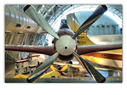
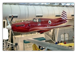
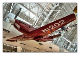
North American P-51C-10 Mustang-Excalibur III (NA-111, AF 44-10947, c/n 111-29080, N1202) circa 2/16/2004 at the National Air and Space Museum Steven F. Udvar-Hazy Center, Chantilly, Virginia (photo by Jim Hough)


Overview
The North American Mustang was designed and built to a British specification and order. The prototype was actually designed, built and flown in 100 days, its first flight taking place in October, 1940. Passing all tests satisfactorily it was put into production before the end of 1940. The first production Mustang I was delivered to the RAF in Great Britain in November, 1941.
The 5th and 10th aircraft off the production lines were taken over by the American Army for experimental test at Wright Field, Dayton, Ohio, and these two aircraft were given the designation XP-51. The first two batches of Mustangs, amounting to over 600 aircraft, were supplied under British contracts but after the passing of the Lease-Lend Act the aircraft were ordered by the American authorities as the P-51 and allotted to Great Britain. On the entry of America into World War II a proportion of the P-51 contracts were diverted to the U.S. Army Air Forces.
North American Mustang I (P-51)
- The Mustang I was fitted with the Allison V-1710-F3R engine rated at 1,000-hp. at 12,000 ft (3,660 m) and with 1,150-hp available for take-off.
- Its armament consisted of four 50-cal and four 30-cal machine-guns; two of the 50-cal guns being mounted in the fuselage, one on each side of the engine crankcase and synchronized to fire through the airscrew.
- All the other guns were in the wings.
- Owing to poor performance at altitude the Mustang I was re-mustered as a low-altitude reconnaissance fighter and posted to the RAF Army Co-operation Command.
- An oblique camera for tactical photographic reconnaissance was installed in the port Backward-vision panel behind the pilot, together with a vertical camera in the rear fuselage.
- The Mustang I made its first operational sortie with Army Co-operation Command on July 27, 1942.
North American Mustang 1A (P-51)
- This was the Mustang I with an armament of four 20-mm cannon mounted in the wings.
North American Mustang II (P-51A)
- Initially the new designation covered solely a change in armament to four 50-cal machine-guns, all in the wings.
- Later series were fitted with the Allison V-1710-81 (F20R) engine rated at 1,125-hp at 15,500 ft (4,700 m) and with 1,200-hp available for takeoff.
- The contracts for this model were equally divided between Great Britain and America.
- From the American P-51A were developed the A-36A Apache dive-bomber and the F-6A photographic-reconnaissance model.
North American P-51B and P-51C (Mustang III)
- These were the first models to be fitted with the Merlin engine and four-bladed airscrew.
- The original conversion was made in Great Britain by Rolls-Royce, Ltd. by the installation of the Merlin 61 engine in the Mustang II.
- The success of the conversion was such that steps were immediately taken by North American Aviation re-design the P-51 to take the 1,520-hp Packard V-1650-3 (Packard-built Merlin 68 with two-speed two stage supercharger and after cooler) which was at that time going into production in the United States.
- The airframe was strengthened to take the new engine, the radiator installation was re-designed, new ailerons were installed and streamline racks for long-range tanks or two 500-lb bombs were provided under the wings.
- The bomb load was later increased to two 1,000-lb. bombs.
- The new design was originally given the designation XP-78 but this was later changed to P-51B.
- The P-51B and P-51C were put into production in 1943, the P-51C at the Dallas plant of North American Aviation, Inc. of Texas.
- The first Merlin-engine Mustangs were delivered to a U.S. Combat Group of the 8th Air Force in Great Britain, on December 1 of that year.
- The P-51B first went into action as a fighter on December 17, and on January 15, 1944, P-51B’s with drop tanks made their first long-range mission as fighter escort to heavy bombers of the 8th Air Force over Germany.
- A modification which had no bearing on the designation was the introduction of the Malcolm Backward-sliding bulged cockpit hood on examples of the P-51B, P-51C and F-6A.
- This modification was undertaken in the British Isles.
North American P-51D (Mustang IV)
- A development of the North American P-51B Mustang with the armament increased to six 50-cal machine-guns, all in the wings.
- Fitted with a moulded plastic "blister" type sliding hood and a modified rear fuselage.
- A later modification was the introduction of a small dorsal extension to the fin.
- This modification was made retrospective for the North American P-51B Mustang, North American P-51C Mustang and earlier North American P-51D Mustang models.
North American XP-51F
- A complete structural redesign of the Mustang as a pure interceptor, to a combination of the optimum British and American strength requirements.
- No single structural part interchangeable with earlier North American P-51 Mustang models.
- New low-drag laminar-flow wing section, new wing plan, improved fuselage and radiator fairing contours, new lightened engine-mounting and landing-gear, substitution of heat exchanger for oil radiator, simplified hydraulic system and cockpit layout, etc.
- Structural weight reduced by 1,600 lbs (726 kg).
- Armament reduced to four 50-cal guns.
- Reduced petrol capacity.
North American XP-51G
- A redesign of the XP-51H, into a long-range escort fighter.
- Higher powered Packard Merlin V-1650-9 engine, which called for a longer fuselage (12 in) and increase in area and aspect ratio of tail surfaces.
- Armament reverted to six 50-cal guns and internal fuel capacity increased with additional fuselage tank behind pilot.
North American P-51H
- Production version of XP-51G with further improvements including a new Merlin V-1650-11 engine developing a maximum of over 2,000-hp with water injection and 150 grade fuel, changes in control surfaces, etc.
- 700 lbs (318 kg) lighter than P-51D.
- Armament six 50-cal guns.
- Can also carry ten 5-in rockets or maximum of two 1,000 lb bombs or two 110 gallon drop tanks.
North American P-51K
- Similar to the P-51D except fitted with the Aero-products instead of the Hamilton Standard Hydromatic four-bladed constant-speed airscrew.
- All built at the Dallas plant of North American Aviation, Inc.
North American XP-82 Twin Mustang
- Consists of two P-51H fuselages and port and starboard outer wings joined together by rectangular center-section and tailplane between the fuselages.
- Pilot in the port fuselage, co-pilot in starboard.
- Evolved as possible long-range escort fighter.
- Span: 50 ft 9 in (15.5 m)
- Length: 33 ft 4 in (10.16 m)
- Weight loaded: 21,210 lbs (9,630 kg)
North American A-36A Apache
- This was an attack or dive-bomber version of the North American P-51A Mustang.
- Development began in June 1942 and the first model flew in September of that year.
- It was fitted with the 1,325-hp Allison V-1710-87 (F21R) engine, and had hydraulic ally-operated dive-brakes and a rack under each wing to carry either a bomb (250, 300 or 500-lb), or a droppable fuel tank.
- Armament comprised six 50-cal machine-guns, two in the fuselage and two in each outer wing.
- The North American A-36 Apache went into service with the USAAF in the Mediterranean just prior to the invasion of Sicily.
- Production was completed in March 1943.
North American F-6
- This is a photographic-reconnaissance version of the North American P-51 Mustang.
- Photographic equipment replaced all armament.
- The North American P-51A Mustang was fitted with the 1,200-hp Allison V-1710-81 (F20R) engine.
- For improved vision certain aircraft of this model were fitted with the Malcolm bulged sliding hood. The North American F-6D was similar to the North American P-51D Mustang and the F-6K was similar to the North American P-51K Mustang.
Specifications and Performance Data (P-51C/D)
Type
- Single-seat fighter and fighter bomber.
Wings
- Low-wing cantilever monoplane.
- North American Aviation-NACA laminar-flow wing section.
- Wing in two sections bolted together on the center line of the fuselage, the upper surface of the wing forming the floor of the cockpit.
- Two-spar all-metal structure with smooth Alclad skin.
- Spars have single plate flanges and extruded top and bottom booms.
- Remaining structure consists of pressed ribs with flanged lightening holes and extruded spanwise stringers.
- Space between spars on each side of center-line accommodates the self-sealing non-metallic fuel cells.
- A structural door is provided in the undersurface of each wing section to facilitate fuel cell installation and removal.
- The rear spar carries the hinges for the ailerons and slotted flaps.
- Metal-covered ailerons, the port aileron having a controllable trim-tab.
- Hydraulically-operated trailing-edge flaps between ailerons and fuselage.
Fuselage
- Oval all-metal structure in three sections: the engine section, the main section, and the tail section.
- With the exception of cockpit armor the fuselage is constructed entirely of Alclad and aluminum-alloy extrusions.
- The engine section consists of two V-type cantilever engine-bearers built up of plate webs and top and bottom extruded numbers, each attached at two points to the front fireproof bulkhead of the main section.
- The main section consists of two beams, each side beam comprising two longerons, which form the caps, and the skin, reinforced by vertical frames, forming the webs.
- Aft of the cockpit the longerons extend into a semi-monocoque structure reinforced by vertical frames.
- The detachable tail-section continues structure of rear portion of main section.
Tail Unit
- Cantilever monoplane type.
- One-piece tailplane with detachable tips.
- Structure of tailplane and fin comprises two spars, pressed ribs and extruded stringers, the whole covered with stressed Alclad skin.
- Rudder and elevators have aluminum-alloy frames and fabric covering.
- Control surfaces are dynamically balanced and have trimming-tabs controllable from cockpit.
Landing Gear
- Retractable type.
- Cantilever air-oil shock-absorber legs hinged to large forged fittings bolted to reinforced ribs and retracted inwardly, the wheels and legs being accommodated forward of main spar.
- Hydraulic retraction.
- Fairing plates on legs and doors forming part of wing contour cover main landing gear when retracted.
- Hydraulic wheel-brakes.
- Retractable tail-wheel is full swivelling and steerable within, range of rudder pedal travel.
Power Plant
- One 1,590-hp Packard V-1650-7 (Rolls-Royce Merlin 69) twelve-cylinder Vee liquid-cooled engine on built-up cantilever mounting.
- Four-bladed Hamilton- Standard Hydromatic or Aeroproducts automatic constant-speed airscrew.
- Coolant (30/70 ethylene-glycol /water) and oil radiators in scoop under fuselage and aft of cockpit with thermostatically-controlled exit-flaps.
- Self-sealing fuel cells (184 gallons total capacity) in wings and self-sealing tank (85 U.S. gallons) in fuselage behind pilot.
- Oil tank (12 U.S. gallons) in engine compartment.
- Droppable ferrying or combat tanks may be installed on bomb racks.
Accommodation
- Enclosed cockpit over center of wing.
- Windshield incorporates an optically-flat 5-ply laminated glass bulletproof front panel with side panels of safety glass.
- Moulded "blister" type sliding cockpit cover.
- Stainless steel sheet and armor plate, fireproof bulkhead in front of cockpit and two-plates of face-hardened steel armor behind seat.
- Cockpit heating and ventilation.
- Equipment includes 24 volt electrical system, radio, oxygen, etc.
Armament
- Six 0.50-in machine-guns, three in each wing outside the area swept by the airscrew.
- Guns are adjusted to converge at 300-yds range.
- Removable streamlined bomb-rack under each wing for bombs up to 1,000-lbs, auxiliary fuel tank or chemical container for smoke making.
- Fusing of bombs is electrically controlled from cockpit and bombs may be dropped in a dive, in level flight or a 30 degree climb.
Dimensions
- Span: 37 ft 0-5/16 in (11.27 m.)
- Length: 32 ft 3-1/4 in (9.75 m)
- Height: 13 ft 8 in (4.16 m)
- Wing area: 233.19 ft² (21.66 m²)
Weights
- Weight (empty): 7,125 lbs
- Weight (loaded): 10,100 lbs
Performance (Packard V-1650-7 engine)
- Maximum speed: 437 mph
- Cruising speed: 363 mph
- Landing speed: 100 mph
- Climb rate: 3,450 ft/min
- Service ceiling: 41,900 ft
- Range (combat): 950 - 2,300 miles
References
- Photos: Jim Hough
- Bridgman, Leonard (ed.), Jane’s All The World’s Aircraft 1945-46, London: Sampson Low, Marston & Company, Ltd., 1945, pp 288c - 291c
- Avery, Norm. North American, Aircraft 1934-1998, Volume 1, Narkiewicz//Thompson, 1998, ISBN 0-913322-05-9, pp 129
- Wikipedia: North American P-51 Mustang article


