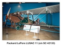


Packard LePère LUSAC 11
Single-engine two-seat WWI biplane fighter
Archive Photos 1
Packard LePère LUSAC 11 (LePèere United States Air Corps) on display at the National Museum of the United States Air Force, Wright Patterson AFB, Dayton, Ohio (Photos by John Shupek)


The Le Père Fighter 2
- Role: Fighter aircraft
- National origin: United States of America
- Manufacturer: Engineering Division/Packard
- Designer: Georges LePère
- First flight: 15 May 1918
- Primary user: United States Army Air Service
- Number built: 30
- Developed into: Waterman 3-L-400
Captain G. LePère, an aeronautical engineer in the French Air Service, designed the LePère Fighter with a Liberty engine for production in the United States. The aircraft was intended for use as a fighter or reconnaissance machine, and carried two fixed guns firing forward, synchronized with the engine, and two Lewis guns attached to a movable Scarff ring surrounding the rear cockpit.
Specifications and Performance 2
General Dimensions
.jpg)
- Span, upper plane: 39 feet 01/4 inches
- Span, lower plane: 39 feet 01/4 inches
- Chord, both planes: 5 feet 6 inches
- Gap between planes: 5 feet 05/8 inches
- Stagger: 2 feet 015/16 inches
- Length over all: 25 feet 45/8 inches
- Height over all: 9 feet 107/8 inches
Weights
- Machine empty: 2,468 lbs
- Pilot and gunner: 360 lbs
- Fuel and oil: 475 lbs
- Armament: 352 lbs
- Total: 3.655 lbs
Performance
- Maximum speed at sea level: 136 mph
- Maximum speed at 6000 feet: 132 mph
- Maximum speed at 10,000 feet: 127 mph
- Maximum speed at 15,000 feet: 118 mph
- Maximum speed at 20,000 feet: 102 mph
- Climb to 6000 feet: 5 minutes 35 seconds
- Climb to 10,000 feet: 10 minutes 35 seconds
- Climb to 15,000 feet: 19 minutes 15 seconds
- Climb to 20,000 feet: 41 minutes 0 seconds
- Service ceiling, or height beyond which the machine will not climb 100 feet per minute: 20,800 feet
Main Planes
- Planes are flat in span and have no sweepBack.
- Top plane is in three sections — a center section over the body and two outer panels.
- Lower plane in two sections attached at lower sides of the fuselage in the usual manner.
- Upper and lower planes are similar in shape, and with ailerons 213/4 inches wide by 941/4 inches long attached to both.
- An interconnecting streamlined rod is used between each pair of ailerons, located between the outer wing struts.
- Leading edge of outer plane is located 49/16 inches from front of propeller hub.
- Middle struts located 945/8 inches from center of machine; outer struts 981/2 inches from middle struts; overhang, 41 inches.
- Interplane strut design is unique, in as much as it eliminates the usual incidence wires.
Fuselage
- Veneer is used for exterior finish.
- Overall length of fuselage, 22 feet 01/8 inches.
- Maximum section at the gunner’s cockpit, 321/2 inches wide, 451/2 inches deep.
- Center of gravity occurs at a point 6 feet 3 inches from nose of fuselage.
- Axel of landing gear 223/8 inches forward of center of gravity.
- The landing gear wheels had a 659/16 inch track and are 28 inches in diameter.
Tail Group
- Overall plan of stabilizer: 983/4 inches.
- Chord: 351/2 inches. It is fixed at a non-lift angle, and attached to upper fuselage longerons.
- Tail flaps or elevators, measure 1581/2 inches from tip to tip.
- Their chord is 313/8 inches, and in addition to this there are small balancing portions extending beyond the tailplane.
- Rudder is 30 inches wide and has a balancing portion above the fin, 25 inches wide.
Engine Group
- A Liberty 12 400-hp engine is used.
- It develops 400-hp at 1,750 rpm.
- Bore, 5 inches.
- Stroke, 7 inches.
- Weight, without propeller and water, 858 lbs.
- Two Zenith Duplex carburetors are used.
- The radiator is located in the upper Plains Center section, and his location has necessitated some slight modifications in the engine to increase the water circulation.
- Propeller, 9 feet 4 inches in diameter.
- Front propeller plate projects 113/4 inches forward of fuselage nose.
- Propeller axis 157/16 inches below top of upper longerons.
- In flying position the propeller hub is 5 feet 27/8 inches above the ground line.
- When at rest on the ground the propeller hub is 6 feet 15/8 inches above ground.
References
- Photos/Drawing: John Shupek
- Jane, Fred T., Jane’s All The World’s Aircraft 1919, Sampson Low, Marston & Company, Ltd., London, 1919 (Arco reprint), pp. 473a-475a


.jpg)