


Percival P.40 Prentice
Single-engine three-seat low-wing monoplane trainer
Archive Photos 1
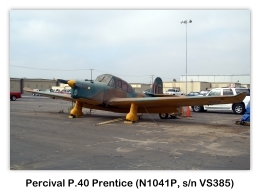
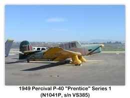
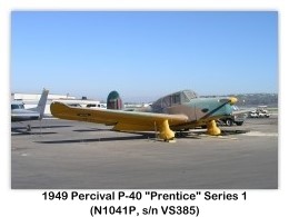
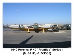
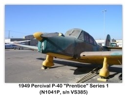
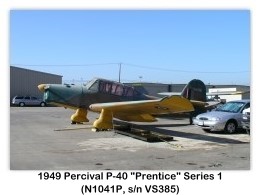
Percival P.40 Prentice (N1041P, s/n VS385) on display at the 2005 Camarillo Airshow, Camarillo, California (08/27/2005 photos copyright © 2005 Skytamer Images by John Shupek)
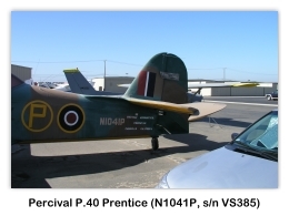
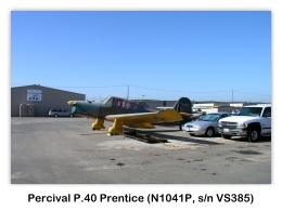

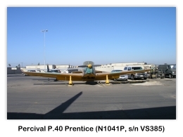
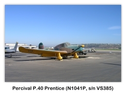

Percival P.40 Prentice (N1041P, s/n VS385) on display at the 2006 Camarillo Airshow, Camarillo, California (08/19/2006 photos copyright © 2006 Skytamer Images by John Shupek)




Overview 2
- Role: Military trainer aircraft
- Manufacturer: Percival Aircraft, Ltd.
- First flight: 31 March 1946
- Introduction: November 1947
- Retired: 1953
- Primary users: Royal Air Force; private pilot owners after disposal by the RAF
- Produced: 1947-1949
- Number built: >370
The Percival Prentice three-seat trainer was designed to Specification T.23/43. The first prototype flew early on 31 March 1946. As a result of flying trials, a number of modifications were incorporated in the design of the production aircraft, including upturned wing-tips, re-designed control surfaces, and provision for an anti-spin extension to the tailplane.
The Prentice was to be fitted with either the 250-hp DH Gypsy Queen 32 or the 296-hp Gypsy Queen 51 engine. The Prentice was produced by Percival Aircraft, and by Blackburn Aircraft, Ltd. at Brough, and by Hindustan Aircraft, Ltd. at Bangalore, India.
Specification and Performance 2
.jpg)
Manufacturer
- Percival Aircraft, Ltd., Luton Airport, Luton, Bedfordshire, England
Type
Wings
- All-metal cantilever low-wing monoplane.
- Wing section R.A.F. 48.
- Aspect ratio 6.94
- Dihedral (front spar) 3° 24’.
- Two-spar structure built into sections attached direct to fuselage.
- Detachable wingtips.
- Spars have light extruded flanges and reinforced plate webs.
- Leading and trailing-each portions made up as complete units.
- Full-depth pressed light alloy ribs approximately 20 inches (50.8 cm) apart with three light former ribs top and bottom between.
- Light alloy steel covering.
- Reinforced root has span-wise stringers to form walkway.
- Ailerons have light alloy D-spar, pressed sheet ribs and fabric covering.
- Trim-tab in port aileron adjustable on ground only.
- Pneumatically-operated split trailing edge flaps and three sections between ailerons.
- Safety device prevents immediate retraction of flaps after baulked landing.
- Gross wing area 305 ft² (28.3 m²).
- Aileron area (total) 24 ft² (2.23 m²).
Fuselage
- All-metal structure in two portions, front portion of rectangular section to aft of cockpit, and rear portion of flattened elliptical section.
- Front portion has sides and bottom built up as a semi-braced structure with light alloy sheet covering.
- Two build-up girders across fuselage form attachments for main wing spars.
- Rear portion is a semi-monocoque structure with light alloy frames, longitudinal stringers and light alloy sheet covering.
- Maximum fuselage with 4 feet 2 inches (1.27 m).
Tail Unit
- All-metal cantilever structure.
- Tailplane has two light alloy stars, pressed sheet ribs and stressed metal skin, and is bolted to fuselage.
- Two-spar fin with main spar bolted to fuselage sternpost.
- Elevators have light-alloy D-spar, pressed sheet ribs and fabric covering.
- Rudder of similar construction with metal covering and with mass balance in horn-balanced portion.
- Controllable trim-tabs and rudder and elevators.
- Area of tailplane and elevators, 57.34 ft² (5.32 m²).
- Area of fin 21.3 ft² (1.97 m²).
- Area of rudder 18 ft² (1.67 m²).
Landing Gear
- Fixed two-wheel divided type.
- Each unit consists of cantilever shock-absorber leg incorporating steel springs and oleo damper, and is bolted to casting on front face of main spar.
- Streamlined fairing over leg and wheel.
- Medium-pressure wheels.
- Pneumatic brakes operated by rudder-bar.
- Track 12 feet 0 inches (33.65 m).
- Tail-wheel carried in full-swiveling self-centering fork which rotates in cast aluminum rocker-arm hinged at bottom of sternpost.
- Steel-spring shock-absorption with Ferodo band recoil-damper.
Power Plant
- One 250-hp DH Gypsy Queen 32 un-supercharged, or 296-hp Gypsy Queen 51 supercharged, six-cylinder in-line inverted air-cooled engine on rubber anti-vibration blocks of steel-tube mounting.
- De Havilland two-blade constant-speed airscrew.
- Cowling in four parts, side panels hinged on top centerline.
- Two 20 Imperial gallon (91 liters) crash-proof fuel tanks in wing-roots between spars with detachable access panels in undersurface of wing.
- Oil tank of 4.9 Imperial gallons (22 liters) capacity in leading-edge of port wing root with oil-cooler inboard.
Accommodation
- Crew of three and ventilated and heated enclosed cockpit.
- Pilot (on starboard) and pupil, side-by-side with dual controls in front, with third central seat for second pupil undergoing air experience behind.
- Standard S.B.A.C seats, front two adjustable.
- Entire cabin top made as complete unit and bolted to fuselage structure.
- Forward portion has direct-vision safety-class windscreen.
- Perspex hood sides Backward for access.
- Side and top panels amber-tinted.
- Front windscreen and forward half of lower panel in sliding hood fitted with folding amber-colored screens for night instruction.
- Rear seat entered through upward sliding door on port.
- Steel-tube crash-pylon between front and rear seats.
- Cabin sides from front arch to front of rear door jettisonable.
Dimensions
- Span: 46 feet 0 inches (14.02 m)
- Length: 31 feet 3 inches (9.52 m)
- Height (tail up, over rudder): 12 feet 10½ inches (3.9 m)
Weights (Non-Aerobatic)
- Weight empty: 3,080 lbs (1398.3 kg)
- Fuel: 280 lbs (130.7 kg)
- Oil: 40 lbs (18.2 kg)
- Radio: 24 lbs (10.9 kg)
- Crew (3): 600 lbs (272.4 kg)
- Equipment: 18 lbs (18.2 kg)
- Weight loaded: 4,650 lbs (1,838.7 kg)
Weights (Aerobatic)
- Weight empty: 3,080 lbs (1398.3 kg)
- Fuel: 280 lbs (130.7 kg)
- Oil: 40 lbs (18.2 kg)
- Radio: 24 lbs (10.9 kg)
- Crew (2): 400 lbs (181.6 kg)
- Equipment: 18 lbs (18.2 kg)
- Weight loaded: 3,850 lbs (1,748 kg)
Performance (DH Gypsy Queen 32 engine)
- Maximum speed at sea level: 150 mph (242 km/h)
- Maximum speed at 5,000 feet (1,525 m): 146 mph (235 km/h
- Maximum continuous cruising speed at 2,200 feet (670 m): 145 mph (234 km/h)
- Maximum economical cruising speed at 3,500 feet (1,066 m): 140 mph (225 km/h)
- Stalling speed (flaps up): 61.5 mph (99 km/h)
- Stalling speed (flaps down): 56.3 mph (90.6 km/h)
- Initial rate of climb: 700 ft/min (213 m/min)
- Rate of climb at 5,000 feet (1,525 m): 500 ft/min (152 m/min)
- Climb to 5,000 feet (1,525 m): 8.3 minutes.
- Service ceiling: 15,000 feet (4,575 m)
- Takeoff run to clear 50 foot (15.25 m) from grass: 390 yards (357 m)
- Takeoff run to clear 50 foot (15.25 m) from concrete: 365 yards (334 m)
- Range at 5,000 feet (1,525 m) at 138 mph (222 km/h): 485 miles (780 km)
Performance (DH Gypsy Queen 51 engine)
- Maximum speed at sea level: 150 mph (241 km/h)
- Maximum speed at 6,800 feet (2,0872 m): 168 mph (270 km/h
- Maximum continuous cruising speed at 5,400 feet (1,945 m): 156 mph (251 km/h)
- Maximum economical cruising speed at 12,200 feet (3,718 m): 155 mph (249 km/h)
- Stalling speed (flaps up): 61.9 mph (100 km/h)
- Stalling speed (flaps down): 56.6 mph (91 km/h)
- Rate of climb at sea level: 9200 ft/min (280 m/min)
- Rate of climb at 5,000 feet (1,525 m): 700 ft/min (213 m/min)
- Climb to 5,000 feet (1,525 m): 7.1 minutes.
- Service ceiling: 18,520 feet (5,640 m)
- Takeoff run to clear 50 foot (15.25 m) from grass (tropical summer temperature): 420 yards (394 m)
- Takeoff run to clear 50 foot (15.25 m) from grass (normal temperature, at 5,000 feet=1,525 m): 390 yards (357 m)
- Takeoff run to clear 50 foot (15.25 m) from concrete (normal temperature, at 5,000 feet=1,525 m): 360 yards (339 m)
- Takeoff run to clear 50 foot (15.25 m) from grass (tropical summer temperature, at 5,000 feet=1,525 m): 435 yards (398 m)
- Takeoff run to clear 50 foot (15.25 m) from concrete (tropical summer temperature, at 5,000 feet=1,525 m): 405 yards (370 m)
- Range at 5,000 feet (1,525 m) at 5,000 feet (1,525 m) at 139 mph (224 km/h): 517 miles (832 km)
References
- Photos: John Shupek
- Bridgman, Leonard, Jane’s All The World’s Aircraft 1948, Sampson Low, Marston & Company, Ltd., London, 1948, pp. 83c-84c


.jpg)